Friday 10 November 2017

Tool explanations

Extrude: (Shift + E) This takes a plane and pulls it out, while connecting the new vertices of the new face, with the old Vertices. Each Vertices are connected by edges, and each edge is connected with faces.

Transform (Translate, rotate, scale)
Translate moves the mesh's current position (Or vertice,edge or face)
Rotate Rotates the current mesh/  Vertices, edges or Face's initial rotation.
Scale increases / Decreases the size of the

Loop cut: Applies new edges calculated in a ring around the mesh.This is typically done inbetween Edges based on your current  orientation (So if your mouse is more sideways on a series of face then up, you're making a vertical series of faces, otherwise, horizontal).

Target weld: Merges the first selected Edge / Vertice with the second, adding edges in order to keep the mesh connected. You can only merge one pair of vertices / Edges at one time.

Subdivision (Add Divisions): The faces selected are split either Linearly (So you choose how many times the face is divided by X and Y coordinates, so a 1 x 3 would have three vertical faces) And Exponential (Which is just an even face division, so 3 x 3 in linear terms)

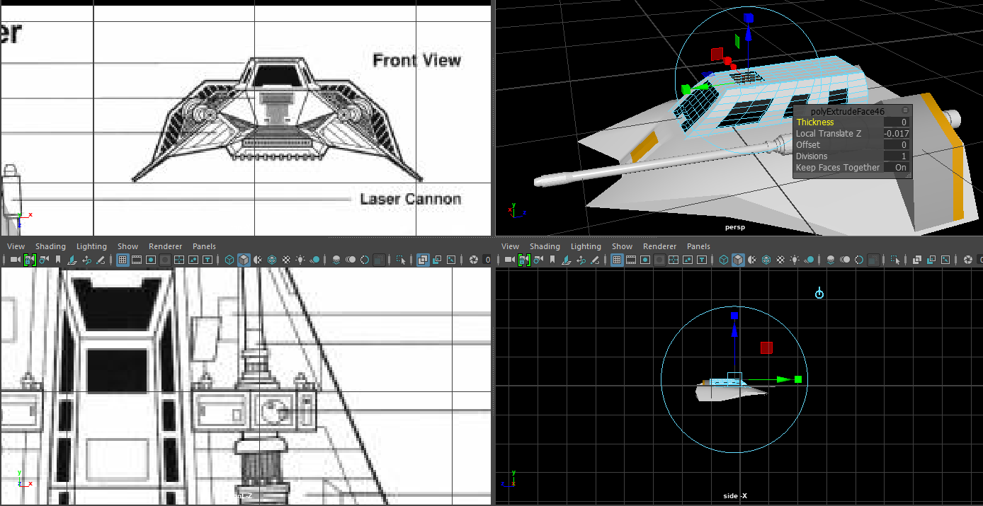
Bevel: Extrusion, but the new face is pulled out and shrunk automatically.

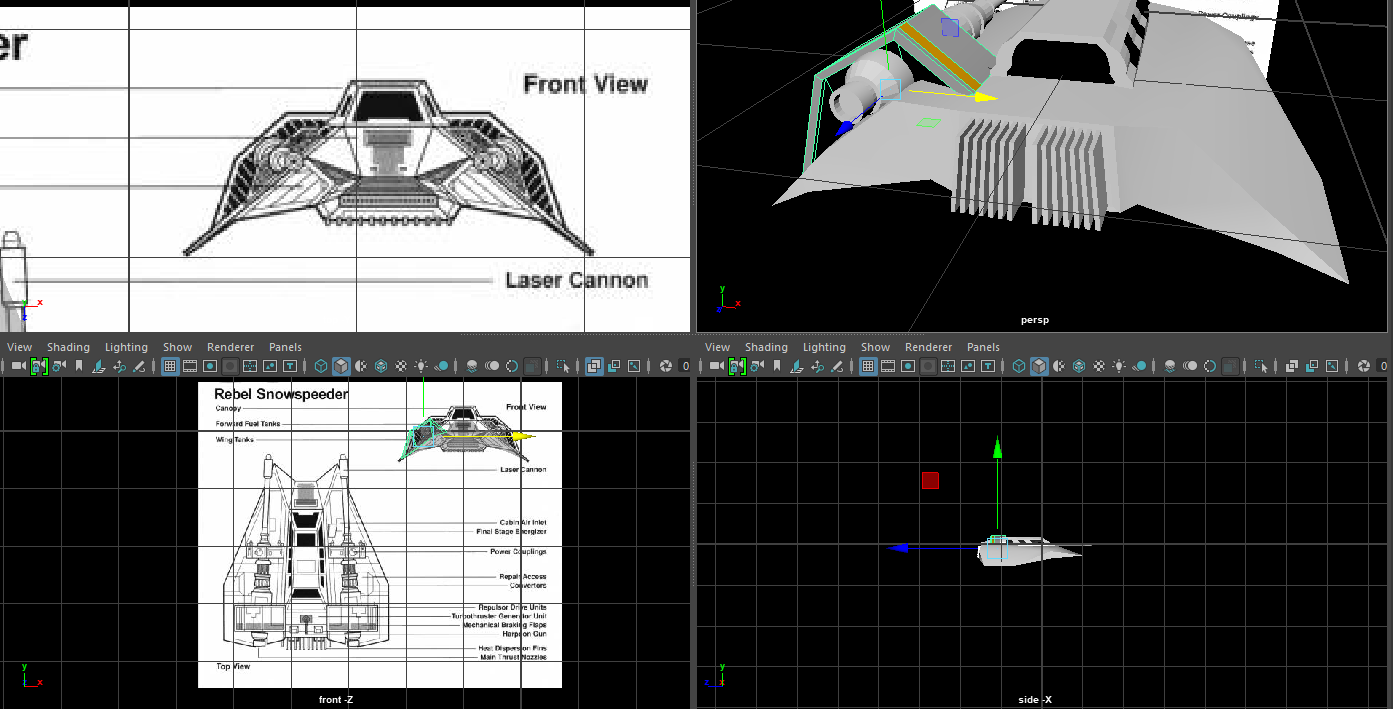
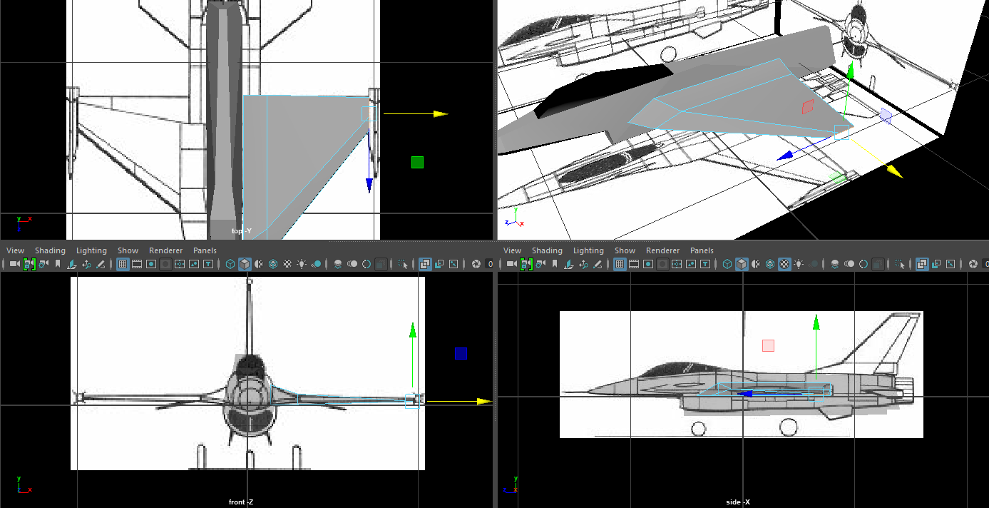
Image plane: Add a 2d Plane with an imported texture (Orientation based on your current camera view)

Mirror: Take the mesh selected, and add a reflection on theother side of the center point.

Center change (Shift + D)Allows you to change the center point of the mesh without moving the faces or vertices themselves.

Duplicate (Ctrl + D): Takes the selected Mesh / Selected Faces, makes a copy, and allows you to Transform said duplication.

Make face / Bridge:Similar funtion, connecting edges with a face.

Multi cut: By far this is a tool I personally adore, this tool allows you to select points on vertices, edges and faces, to make a chain of new vertices and edges (So for adding detail, like cutting out something on paper)

Flip: Like mirror, but it doesn't create a duplicate, it just flips the existing mesh's co-ordinates. (Not used)

Create Primative: Adds in a prefab mesh (so Cube, cone, torus etc)

Slide Edge: To be perfectly honest,this is a redundant tool, as it's only task, is sliding down an edge, which you can already do with the transform tool. (Not used)
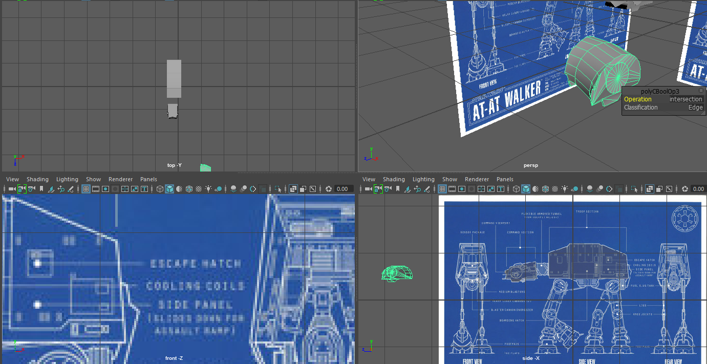
Booleans:

Union: Combine two meshes and remove any intersecting vertices and edges(While making vertices and edges to make the mesh seamless)

Difference: The first model selected's mesh is edited with so the second selected mesh creates an indent, With intersecting vertices, edges and faces on the second mesh remaining, while the first mesh's intersections are removed.

Intersection: Any intersecting vertices, edges and faces are kept, any non intersections are deleted.


Wednesday 8 November 2017

Booleans!


Union.

Union is a useful tool that allows for Models vertices to be combined seamlessly and without clipping. For this, the torus shape what was clipping through the mesh, Both are now the same object, with their vertices merged, Any edges or verticles that were on the inside are gone, leaving only a clean outer shell.

Difference

Difference is a rather interesting tool, that allows for you to make dents, holes or even marking in meshes, an example would be a face print in a rock or mud. Any intersecting section of the models are deleted, but this depends on the order of which the models are selected.

For example, if I chose the head of the AT AT first, it would not be deleted and it's core vertices would remain.

BUT, if I selected the torus first, the torus would remain (Like in the picture below) While the head of the AT AT is deleted.


Intersection.

Intersection is like the exact opposite of intersection, where any faces and vertices that ae clashing, are kept while the non clashing vertices are removed. This of it like taking a container over jelly, taking out a section of said jelly. You have what the container managed to overlap with.

Creating the snowspeeder

This will just show the basic development of the snow speeder!

The development will take multiple parts,the chassis, the canons, the cockpit and the exhaust parts of the cannons!


First like all creations, we start with the cube,  and we extrude the  mesh to fill out one side of the chassis, the goal is to get the basic 2d shape.


And after the 2d  shape,  wecan begin editing the height of the points  (We used the mirror tool to get the other side of  the Chassis, without any complications)


Adding an orange material to the front...  Don't worry, there's more orange to go around
And later on I will be replacing the default material with a shiny white coat...  But not until I get a few more pieces made


Next up is the Cockpit, very simple, get a cube, put it into a trapezoid like shape, And then subdividing the top and side faces (By 3,that will give us enough detail to make the windows) In which we'll mark them out with a reflective black glass like texture, and then extruding those faces in, to make the glass look like it's not just painted on.


Next up the Cannon... And admittedly, I forgot to take screenshots of creating it...But I  can say I simply took a cylinder, and began extruding the  end face, expanding it, pulling it out, depending on what kind of shape I wanted it to take.  I started from the cannons tip, and worked my way down to the base, Extruding, pulling out, pulling back if needed. But this is  just for the simple pipeline,not the exhaust, that comes later.


Next up  is the creation of the exhaust from  the cannon, and the exhaust from the Chassis, basic stuff, for the cannon exhaust we used a Cube, made it into a cuboid, divided by three by the V (I believe that's vertical) which allows for the orange strip you see. And at this point I merge the Cannon and it's exhaust, to make it one object. As well as duplicating it, moving it to the opposite side of the model, scaling the model by negative one (To make it face the opposite direction)


Now personally, This model bothers me I am done, mesh wise, there is nothing more to add apart from bump mapping and texturing, but.. It seems like I should be making itmore complicated with more poly's.

Yes, the cannons and engines are very detailed,  But the body, while it's a simple shape... it just seems like there should be more.

But adding more to the Chasis, would cause issues.


F16 creation

F16 creation.

Ok, so creating the F-16! First step is downloading the top, side and front view of the F16 Base (Space, click on a view, import image  plane,boom, you have a plane)


First we'll makethe body, so using the perspective vieew and the top view , we're going to shape up the general shape of the F16, Which mainlyuses Edge pulling, Extrusion and a target weld for  the nose of the jet.


After we finish (Admittedly a low poly F16 Chasis)
We're going to progress into the wing (One wing,because we're going to mirror it onto the other side)


And then the small rocket onthe tip of the wing., Which we'll merge later on.


08/11/2017

Ok, so I just went back to check this, to see if I finished... And I'm not  done, I forgot to make the tail!

Which we have two methods to make:


A:Make the tail wing as a seperate model, and just make it that way.

B: Extrude from the tail end of the model, Pull out and pinch as appropriate.

ANd I did the latter! Because it was much easier than making a new mesh in order to union, And it got the same results!.

And the jet engine, very simple a cylinder, one side scaled down, extrude the not scaled down side, and get it to fit as appropriate.

And that is how you do a low poly F16, I actually liked this little task, it was simple to do, easy to finish. Although... My documentation clearly let me down, as I stopped halfway through, and I had to do a lastminute update.

Curves and NURBS Plus motion pathing


Now we get onto the interesting stuff! so first off, we have to draw a curve (Modelling, Curves, draw curves, it's a pretty simple thing) and this curve will be showing the movement path of the snow speeder we're going to have fly off into the Imperial star destroyer!


But we just drew it flat as a 2d drawing, so, we want to select the curves, right click it and begin editing the curves vertices, allowing for rises and falls, or minor tweaks to the pathing if need be.


Now, for the parenting... First up, you select your object you want to move, then you select the curve (The object will always go from first point to last, so if you drew your curves backwards... Woops) Then you go into the animation path, Constain tab, motion paths, then attach to motion paths... And boom, you're done! Your object now follows the path dictated... And best part, it can be edited at any time!... Just... Be careful.


But now, we want a good camera angle while the ship is racing, so, we put the camera next to the mesh... Aim it the way we want... And we simply, parent it... And boom our camera follows the snow speeder!... But you can still turn and move it on it's own, but it's actions are now tied to the snow speeders.
And here's the foggy background!.. Which I will show, in my materials post!


This scene won't be in the final product and is just a test and a general experiment with curves and the scene as a whole.


Also, you can choose to edit the points of the curve directly, that way you can get the precise endpoints you want, instead of affecting the curves in a weird way.


In the actual Animation, the Snowspeeder is actually set to the motion path as in this test animation (Pathing is different obviously). But along this way I discovered a few vital pieces of information. For starters motion pathing is incredibly finicky if you're doing anything more complicated than a turn, or a snake like manoeuver. I know this because during the animation, there's a spiral part, where the snow speeder turns with the pathway, to give some style to the animation. But instead...

The snowspeeder at one point curves completely wrong and begins to move the ship in a completely wrong rotation. This was then resolved in post by masking this effect, But still, Motion pathing is more used for simple movements, Like running, driving and so on, not so much anything stylized.

Tuesday 7 November 2017

Intro + Moodboard+ Storyboard

Introduction.

Hello and welcome to the Maya blog! I'm going to be incredibly blunt, this entire blog is my learning experience with Autodesk Maya. Which I should mention I have used before, not to any decent extent, but I have used it before.

First of all this entire blog will be posted in weeks, 1 to 12 specifically. I will post on the planning, techniques, actual implication of said techniques to the best of my abilities to fufill the unit.

And Disclaimer: All the work in this unit (And shown in the blog) is 100% mine, Unless I'm posting inspirations about the project (E.g. Models I want to recreate I.E. Pod racers, X wings etc.).

Moodboard:


Storyboarding
The first step of the animation creation is planning what the heck is actually going to be shown, you cant just start an animation aimlessly. So for my animation I have decided to do a more action based rendition of the battle of Hoth. But will include the same actors (Snow speeders, Tie fighters and an imperial star destroyer..)
The basic premise for the animation is as follows.


The plot starts off with a shot of the  Imperial star destroyer flying through a canyon with tie fighters flying around it, as they advance forward through the snowy terrain.

The camera pans from the back to the side view of then, showing the advancement of the Ships heading to their destination.

Next scene is a panning down shot of an ice like road, which after waiting a couple of seconds, a snow speeder following the path zooms off, until off screen.

The camera then pans to a side view of the speeder, looking at the drop off, seeing the star destroyer and the tie fighters flying slowly past. with the ship suddenly dropping down, flying down a spiral of ice, getting faster and faster as it reaches the bottom.

When the speeder evens out, it flies forward into a wall of ice, firing a couple of lazers, causing it to shatter, revealing a ramp, which will launch the speeder upinto the air, where the speeder shoots down two tie fighters,which crash down into the star destroyer, causing it to crash.

Saturday 4 November 2017

Tie fighter


Creating the tie fighter.

First off, I'm splitting this model into three pieces,The center, the Wings, and the joins from center to wings. So I only need to make 3 meshes, duplicate the wings, and then mirror their position.


Now, I'll go make the base for the mesh that connects the cockpit to the actual wings, As well as a sphere for the cockpit, rotated 90 degrees on the X axis to have the north point facing the front (So  I can do the proper shapes later.


Next the cylinder shape,  Again a base shape, until I get everything ready.


Now for some wing work,I'm adding the metal  frames, which is a cube pulled out, with extrusions for the inner details.


In which the tip is target welded together to  give a sharp blade look,like the wings are actually designed. Which will be later have material added.


And now the center piece, which was a Cylinder,  with the max radius faces dropped from 20 to 6, leading into a Hexagon shape... Which has the front face extruded, for the smaller Hexagon.


Next up, the cockpit frame, which is simple, I take the middle faces on the very front,and four faces (so  2 x 2), skipping one row of Columns, for the next 2 x 2 until we wrap around fully, leading to the frame like design.


And now... An admission of flubbing up precision in detail. Which was me just over complicating the model... You see, I boolean differenced the top of  the Tie fighter, and added the top half of a sphere,  thinking I needed that shape for the top... When in actuality... It's kind of a mix.
To do the flat part of the sphere, I needed to cut the  top... BUT, to do the indents, you need the side of the Sphere, so,I've just did some indents in the same position as the original, according to the blueprints. But... for this instance only, the model has strayed from the original blueprints.


Some alterations to the connection to the wing, trying to make it as close to the schematics as possible.


Adding a jet engine tot he back of the cockpit, Extruding a ring near the back, and then pulling out. Other alterations used Subdivide and extruding.


And, I beleive this should be enough detail for the Tie fighter, as the fighter will be in constant motion, Even blurred, All that's left is putting everything together with boolean.


Oh and before I forget,fiddly details, I believe this is a pipe to power the ship (Since the wings are solar panels, it would make sense for this to be like so) And yes, I undid the mirror process... But... that's so I don't have to manually make these changes.


And finally... THIS is the final product! From a distance, it looks pretty accurate! It looks like a tie fighter, Only thing that's off is the lack of textures... But for now, the textures can wait, since the goal for the first hand in, is to make the model, not to texture and add material,but that won't be so hard to add.


Also the model's wings, and body are not connected, just incase an issue occurs that needs a quick fix.

Now I personally thing I did really well on this model, and I'l actually proud of it! There's enough detail on the mesh itself, that I'm actually happy with it! And personally my favourite part of this mesh, was making the cockpit, Even if I did mess up the top of it... And since it's a minor piece, maybe I overkilled the amount of poly's this mesh needed.