Friday 15 December 2017

Imperial Star destroyer - Updated

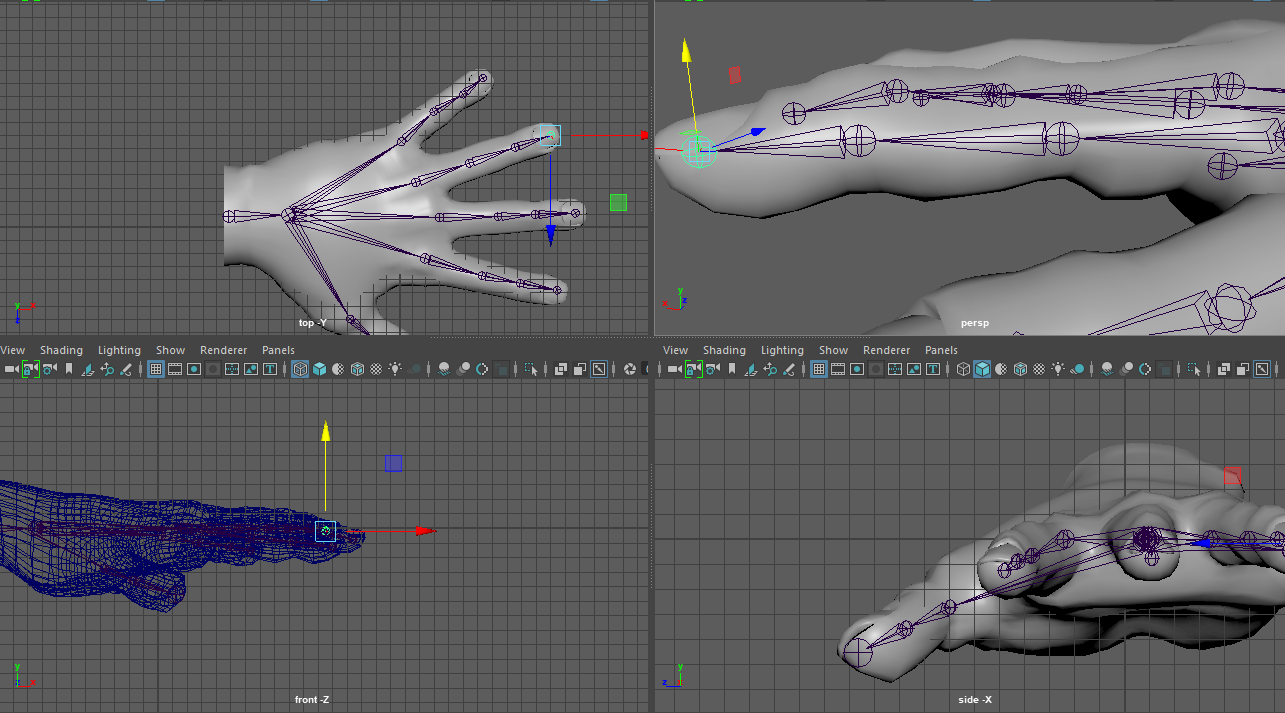
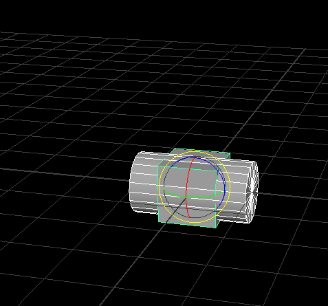
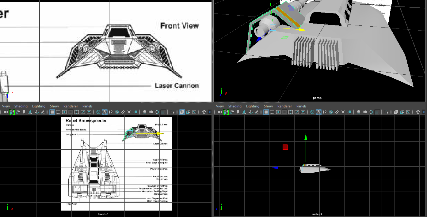
Step one,setting up the blueprints, and the cube... 
 Centering the cube in the center of the images,allowing for a visual guide for themodel.

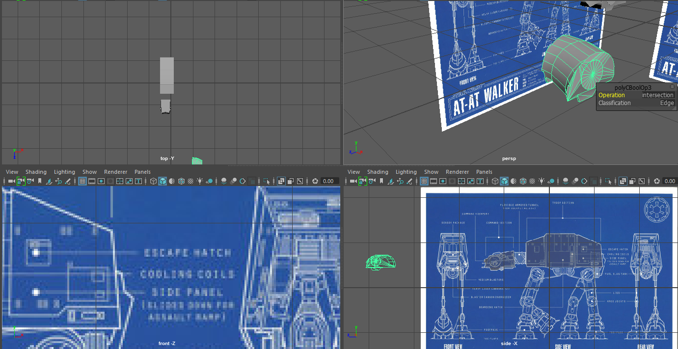
First off,extruding the cube, subdividing face to give the triangle shape, reason I didn't use a pyramid was because I believe going from cube to shape is easier than shape to shape... 


Next up extruding the sizes to give the small indent in the sides, to follow the instrutions in the blueprints. Which was simply made my selecting the side faces, then subdividing horizontally, and scaling inward (X,Y only)


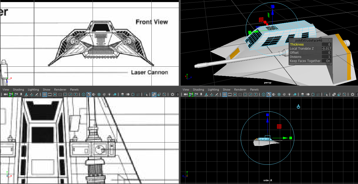
Next, we need the cockpit, at least that's how I'm identifying it for this process, we have a total of three layers, Which will be made with one mesh, for simplicity, Also so it melds will with the base model below.


Next we'll bemaking the control sector which is connected by a vertical shaft,whichis simply doneby more extruding!

Next up are the side bobbles... Or whatever they're called, simply thing, we're getting a sphere, reducing the poly count until it matches the orbs in the back, followed bysome Cylinders (Again to match the shapes)


Give the orbs a platform, boolean union them until they're one prefab, then stick them into position.


Next up, the engine and exhaust. Which is simply, a cylinder, with one side scaled down to give the cone effect. Extruding the larger circle of the cone, BUT do not pull it, inside scale it down, Extrude again, pull out, scale out, THEN we Extrude one final time, extrude down, and pull in.  And that's how you get that shielded rocket kind of look.

As for other details like the rings and the bars,  simply Halo's and Cylinders. Nothing too complicated.


And that's the general shape of the Imperial star destroyer! Personally I feel like there should be much  much more detail, but I either: Can do it easier with Textures and bump maps. Or  the extra modelling work would lead to either complications, or inaccuracies with the model.  But over all, I had fun working on this model! Even though issues with the Side of the destroyer gave issues, cuts not connecting properly, and somethings the mesh breaking at points.

If I had to pick something I could have done better, I'd say time management, as I spent a lot of time deciding how to get the body done.Since, while the shape is simple, getting the control cockpit, the extra layers, I wish I could have done it on the actual model itself.


Now, an update... So the star destroyer I made previously was borderline buggy and pretty bad, so for the animation, I decided to completely remake it.


This was made, using the same tactices as before, but with more emphasis on having this model off in the distance. I used Bumpmaps to give the star destroyer more texture, I centered the model's faces so it wasn't lopsided like the other one. Redid all the Textures so it wasn't just one texture wrapping the star destroyer which made it completely ugly. (A top image for any face on top, and a bottom image for the underbelly). More details like lights to represent actual rooms in the star destroyer looking to the outside. Modeled the center a bit more again to be more accurate to a more detailed Star destroyer. But the rest was merely to give it the look from a distance, as you don't get any closer than panning shots from a fair distance, no close up shots involved.

If there was any close up shots, more details like the cannons would have to be actually modeled, the bumps would also have to be fully modelled and not passed onto a texture and a bump map. In reflection, I probably should have taken more time and care with this model, Using my head in how I could have made it look good, and not just aim to fling something "Decent" out. I decided to change the model due to some animation issues, where part of the model wasn't in center... But that was it's center. And instead of dealing with the broken ship, I got rid of it, and remodelled a completely fresh one.


Skeleton Rigging

First, we were given the skeleton hand from the lecturer, No skeleton.

First, I made the base bone at the wrist of the hand, which was doneby going into the Rigging section of Maya window options, going into skeleton, and going into create joints.

When I make  the first joint from wrist to center hand,t hen center hand to middle  knuckle, by just clicking the points I want the next joint to appear at. And like any hand, the thumb has the base joint and the middle  joint, while  every other finger has three joints, to simulate a real  lift hand properly.


And to simply start the other fingers, I simply hit the up key to go up in the  Skeleton Hierarchy to go back to the center bone, then making the next finger,  and so on and so forth, until all the finger bones are created in the rough spot.

Next it actually changing the bones to match the model itself, so grabbing the bones and just changing it's position, starting at the base to the tip of each finger, since working from finger to base would require more editing on the finger sides, since each bone is a child to the bone before, meaning any movement to the parent would change the childs location. The following two pictures are the before and after bone editing. 

As for the way the fingers are located, I based the bone structure on the actual way the  human  hand is shaped,  where the bones originate from the base of the hand for all fingers.


Next  up is rigging the bone itself, first you select the bone structure, the base bone. Followed by additionally selecting the hand mesh, then going to skin, and you can either go bind skin, or interactive bind skin.

Bind skin allows you to bind the skeleton with the default calculations to get to animating immediately, while interactive allows you to change the weight of  each bone, so you can choose what parts of the  mesh are affected. For the hand I went for Bind skin, and the default bones were enough to get  the fingers and thumbs to animate properly.

The following few pictures are me simply bending the fingers and thumb to prove that the binding was successful. Although if this wasn't the case, I'd have to do the interactive bind skin, and simply mess with the weight  and areas until every bone moved properly.

This is actually a pretty good technique to use if you have multiple limbs or parts of a mesh that have to move relatively realisitically. However, for my animation, I didn't use this feature, not because it was hard to do, but I just didn't have the mesh I actually needed for this.Like an AT AT or an AT ST which would require limbs to move.


Thursday 14 December 2017

Bouncing rubber ball / Key frame animation.

Animating the ball, a fairly simple animation, using Keyframes (Set with the S key on the timeline)
First off, we have the display for the frames, numbers one to 31. For starters, I'll fully animate frames 1 till 7, then I'll animate frames 12,17,21, etc (Basically all the balls that aren't grey)


As you can see, rotating and stretching the ball to fit frames 5 and 6, to give that sense of speed and velocity. Only to be squashed. Now putting all the black ball frames in place,I'll run the animation, and... The ball doesn't exactly morph as projected. This is because the animated ball is trying to transition to frame 12, calculating frames 8 to 11 from the 7 start, to the 12 end.


But to get the animation to work properly, we'll need to fill out all the grey frames in order to get the animation to work out as intended.


Now in the actual animation, I've actually key frame animated a few things in question, for example the Star destroyer was using keyframes as this allowed more accuracy in movement than motion paths. Although it's more tedious with alot more input required.

But it allows for more sudden actions that tween from one key frame to another.


Constraints and relations


Aim:
This allows the main object to face forward (Object Axis Z) to the target object, like the camera aim.  This could be good for eyes rolling to track something, a turret aiming at a ship. This is actually set within the Camera functions within Maya. With the Camera Aim, and Camera aim and up. Essentially a shortcut to aiming.


Parent:
This puts the additional objects under the hierarchy of the first selected, meaning whatever movement the parent object does, the children are affected based on the parent's axis.

An alternative would be going into the hierarchy and drag and dropping objects into the parent you want within the Hierarchy view in Maya.


Scale:

Pretty simple to explain, Constrain rotation matches the scale of the child / children objects with the main parent object, Rotation, location aren't affected, as this is  based on local scale. (So Object X instead of world X)  This is good for


Rotation:
Constrain rotation will simply mean the linked objects will share the same rotation, Location and scale are unaffected. This is kind of good for having a group of objects  moving at the same time. This is good, so you can animate one spinning object, and simply have the other objects rotate in the same way. Without having to individually rotating each object one by one.

Translation: This... Is the one I don't really get, this puts an object in the same position of another. No position change allowed, which,personally isn't  as good as just doing a basic parent/ child relationship.


Sky dome

Making a sky dome is actually pretty easy (And considering I did it in my animation I will just show my skybox)

First, you need a sphere, and a skybox material, and like setting any other texture, you simply add the texture to the Material's colour variable, And since this is a sphere, we simply need to do a spherical UV bind to it, very very simple.

But now, the texture is on the outside of the mesh, and when you look on the inside, it's simply black. So we simple have to select the sphere in question, right click, and simply invert the faces of the sphere, next time you render inside the skydome, you now have a sky surrounding your scene! Instead of a flat colour.

Or an alternative would be setting a background to your renders, but this will only lead to a simple static image that won't move to your perspective.

It's nothing complicated, infact it's a very easy technique to use in any engine, Maya, Game engines like Unity... And it's cheap and effective to use. Although, make sure you get the right image to set, otherwise... You can get very strange visuals.
(Non maya visual from Mount and Blade)

https://www.reddit.com/r/gaming/comments/2pdiqc/a_strange_glitch_my_friend_experienced_whilst/?st=jb744gty&sh=51bd2424

Image result for Sky face texture

Rendering / Post rendering.

Test view: This is the scene I'm demonstrating, the camera directly infront is the close angled Lens, while the one to the side is the wide angle, this is just to  show off different aspects of rendering, which will be shown shortly.


Vector: Simple Geometry, no shading, the default colours, no glow no special effects. This special rendering style is actually used in South Park episodes, simply shapes, simple movements, no shading  needed.


Shake: This simply changes the position of the camera slightly using X,Y Co-ordinates, this is a good way to mimic a bumpy ride, by having the camera shake even Simulating an earthquake by purely making it shake up and down.


Software: Software is a smoother rendering method,  but cannot do too many details, smoothing is disabled on objects. Lighting is disabled, but textures can be rendered, as well as certain special effects such as Particles.


Hardware: While Hardware is a more indepth way to render,  rendering lighting, textures, shading, special effects like glows. Smooth rendering can occurs


Wide lens: Changes the way the scene is rendered, making the subject in question smaller, while rendering out whatever would have been cut out. And the opposite is true for The zoomed in lens, where the focus is zoomed in on, and anything around is essentially cut out of frame. Different camera lenses can make thedifference between showing a wide shot of many people, making them seem far away, while the close up lens allows you to focus on details, close up. And this all can be accessed in the rendering options.


Next up, the actual rendering process, Here are the following things you need to use to render:

Camera.
Start and end frame. (Beginning and end)
Render type. (Software,Hardware or Vector)
Single frame render or video. (Save as one single frame, or from start to end frames)
File type (Png, AVI,etc), file name.File Location. 
FPS (Frames per second)


Now as for my actual animation, I decided to go with medium quality animation, partnered with medium lighting (To speed up rendering time). I am initially rendering out every 200 frames. So I can stitch them all together as I need them. I will render out frames 1-200, then 201-400, and so on and so forth until I hit 900 (30 seconds) So that means I am rendering 6.6 seconds each avi clip. Although the rendering seems to stop at frame 639 for some reason, so I'm trying to skip frame 639, due to it causing render crashes. It only seemed to be on the snowspeeder camera, so my solution was to switch rendering to a different camera, and it seems to have worked, no idea why this happened however, just a weird glitch where the rendering thought it was finished when it really wasn't.


My settings are set to 720p HD settings, so the width and height are within the requirements of the assignment, as well as my animation being 30fps, again, the requirement for the assignment.

I was originally rendering out the animation in one big chunk... But the animation would crash before it reached that point, so I changed to rendering in chunks (At a lower shading quality too) This was to make it so I should at the very least have something from a rendering session, instead of losing everything just to try again, wasting more time than I already did.


The plan for all the animations is to have editing done post (So motionblur, screen formatting, audio etc). I have multiple camera angles (If I can render them all) to show different perspectives of the actual animation. 
Now for what's actually happening in post rendering (Editing in other words). First of all the editing software I'm using is Adobe after effects, as I've had previous experience with this editing software before. I decided to do a few simple edits. One being snow in the scene, thanks to a solid black layer, I get to set a layer of snowfall, something for the background. But I have the black removal on so the snow is overtop of the video file, without any issue. Additionally in one part of the animation I decided to add a lensflare, to mimic the effect of a blast, like a bomb going off in the distance. As the Star destroyer and Tie fighters can be seen later fleeing the scene.

An actual scene of mention is the first scene, which actually uses a fair bit of exposure effects, starting from a bright light, eventually fading until it shows the ships, the target of the animation. This actually did require a reshoot, as the animation the first time, wasn't rendering the right camera... A negative to Maya, where changing the rendering camera is much more complex than other software. Meaning I missed an entire scene, and I needed to rerender, wasting valuable time.

Next patch of editing is actually when I start to use a couple of adjustments layer, These are essentially edits to any layer below, mainly I did a fair bit of warping of the screen after hitting a giant snowboulder on the way to the ramp. This was admittedly a way to hide one of the flaws of the original rendering going down the spiral, at least for part of it. But I decided to add some error text, explaining what's going on with the visuals, since the Camera's going through issues. Which was placed above the warping adjustment layers just so the text was untouched. While the snow effect was below the Adjustment layer, so you don't see random flakes of snow during the warping process, kind of throwing off the illusion of a video glitch. In addition for the ending, it's a news broadcast of the imperial star destroyer, with the logo and a BBC styled text banner, acting as an overlay, which comprises of an image with a transparent background with the banner, some scrolling text, which is also made with after effects. And finally the imperial logo, edited to be red to match the banner. The text changes during crucial points of the broadcast, thanks to keyframing values, like the camera reboot sequence. And during this star wars imperial march (Link: https://www.youtube.com/watch?v=qYPIf8UE0wc ) is playing in the background, and when the broadcast begins to get interrupted, the music also begins to distort. 

Next post effects editing was quite simply put, changing the speeds of clips. So for example if the rendered scene is a bit too slow, I can speed up the clip by going into Layer, time, time stretch. This is essential to this animation, as certain parts as rendered take too long or not long enough to actually take effect. and is much easier and faster to edit than rerendering.

And one technique which is... Cheaply done, was the fire and explosions effects, this was made using greenscreening techniques, which actually looked good, apart from being a completely different style than the animation itself, due to the fact it's a real explosion and real fire. But in the end, I kept the flame on point, kept it rotated and scaled as I needed it, and it looked pretty ok. Alternatively I would have used Particles for smoke instead, but.. In the Particles blog, I already mentioned the issues with Particle emitters in Maya.

Particle emissions / Lightning / Volume materials.

Particle emissions.
Personally I tried to use this, but the animation seems to be having issues, as I'm writing this, but Particle emissions basically produced a 2D texture (Dots, Streaks, spheres etc.) based on a spawn point and an area of spawning, which allows the particles to actually spawn, since without the area, nothing spawns. Before issues began to arise I managed to make a pretty good smoke like effect to mimic a smoke like fire. Originally I was going to add this for the Star destroyer when it's destroyed, but it seems to have caused an error with rendering, so I removed it for the Snow speeder perspective.

Now a complaint about Particles, As they cause Maya to crash constantly. Skipping along the timeline, back and forth, The particles won't react appropriately, Already spawned particles will remain if you go back in time (When those particles shouldn't exist) Particles will fail to spawn if you go too fast forward, missing their cue. And finally if you run through the animation, there is a high chance the actual software will freeze. Meaning if you want a smoke or spark effect, probably best to use Post render editing to help (After effects, vegas pro etc.)

Lightning.

Lightning is one of the effects I chose to use for my animation, specifically to show the tie fighters took damage from the snow speeders shots, to the left you will see the lightning in the modelling viewport, while to the right you will see the lightning render. very simply to impliment, simply select to objects you want lightning between and use the Lightning effect tool. By messing with the material you can have anything from blue, green or red lightning.

Sadly this can only be rendered out in Software mode, meaning any hardware based effects wouldn't be rendered.


Volume Materials.
Volume Materials is a way to make a simple fog effect. In terms of Maya, it's a NURBs primative with the volume material set instead of the surface, which by default is set to be thicker in the center of the object, only to fade near the edges. From the objects you're allowed to use, cone, cube, sphere, pyramid. Personally, I used the cones with some emissive materials on the tie fighters to mimic flame flickering. A Volume box to make the valley you saw in the last image, filled with fog. A sphere for a fire like glow, Like if you were looking at an explosion or a sun.

This is the best way to actually add in a easy to set fog affect in the background, without adding one post edit... And messing with Layers and affects just to get a simple fog.

Friday 10 November 2017

Tool explanations

Extrude: (Shift + E) This takes a plane and pulls it out, while connecting the new vertices of the new face, with the old Vertices. Each Vertices are connected by edges, and each edge is connected with faces.

Transform (Translate, rotate, scale)
Translate moves the mesh's current position (Or vertice,edge or face)
Rotate Rotates the current mesh/  Vertices, edges or Face's initial rotation.
Scale increases / Decreases the size of the

Loop cut: Applies new edges calculated in a ring around the mesh.This is typically done inbetween Edges based on your current  orientation (So if your mouse is more sideways on a series of face then up, you're making a vertical series of faces, otherwise, horizontal).

Target weld: Merges the first selected Edge / Vertice with the second, adding edges in order to keep the mesh connected. You can only merge one pair of vertices / Edges at one time.

Subdivision (Add Divisions): The faces selected are split either Linearly (So you choose how many times the face is divided by X and Y coordinates, so a 1 x 3 would have three vertical faces) And Exponential (Which is just an even face division, so 3 x 3 in linear terms)

Bevel: Extrusion, but the new face is pulled out and shrunk automatically.

Image plane: Add a 2d Plane with an imported texture (Orientation based on your current camera view)

Mirror: Take the mesh selected, and add a reflection on theother side of the center point.

Center change (Shift + D)Allows you to change the center point of the mesh without moving the faces or vertices themselves.

Duplicate (Ctrl + D): Takes the selected Mesh / Selected Faces, makes a copy, and allows you to Transform said duplication.

Make face / Bridge:Similar funtion, connecting edges with a face.

Multi cut: By far this is a tool I personally adore, this tool allows you to select points on vertices, edges and faces, to make a chain of new vertices and edges (So for adding detail, like cutting out something on paper)

Flip: Like mirror, but it doesn't create a duplicate, it just flips the existing mesh's co-ordinates. (Not used)

Create Primative: Adds in a prefab mesh (so Cube, cone, torus etc)

Slide Edge: To be perfectly honest,this is a redundant tool, as it's only task, is sliding down an edge, which you can already do with the transform tool. (Not used)

Booleans:

Union: Combine two meshes and remove any intersecting vertices and edges(While making vertices and edges to make the mesh seamless)

Difference: The first model selected's mesh is edited with so the second selected mesh creates an indent, With intersecting vertices, edges and faces on the second mesh remaining, while the first mesh's intersections are removed.

Intersection: Any intersecting vertices, edges and faces are kept, any non intersections are deleted.


Wednesday 8 November 2017

Booleans!


Union.

Union is a useful tool that allows for Models vertices to be combined seamlessly and without clipping. For this, the torus shape what was clipping through the mesh, Both are now the same object, with their vertices merged, Any edges or verticles that were on the inside are gone, leaving only a clean outer shell.

Difference

Difference is a rather interesting tool, that allows for you to make dents, holes or even marking in meshes, an example would be a face print in a rock or mud. Any intersecting section of the models are deleted, but this depends on the order of which the models are selected.

For example, if I chose the head of the AT AT first, it would not be deleted and it's core vertices would remain.

BUT, if I selected the torus first, the torus would remain (Like in the picture below) While the head of the AT AT is deleted.


Intersection.

Intersection is like the exact opposite of intersection, where any faces and vertices that ae clashing, are kept while the non clashing vertices are removed. This of it like taking a container over jelly, taking out a section of said jelly. You have what the container managed to overlap with.

Creating the snowspeeder

This will just show the basic development of the snow speeder!

The development will take multiple parts,the chassis, the canons, the cockpit and the exhaust parts of the cannons!


First like all creations, we start with the cube,  and we extrude the  mesh to fill out one side of the chassis, the goal is to get the basic 2d shape.


And after the 2d  shape,  wecan begin editing the height of the points  (We used the mirror tool to get the other side of  the Chassis, without any complications)


Adding an orange material to the front...  Don't worry, there's more orange to go around
And later on I will be replacing the default material with a shiny white coat...  But not until I get a few more pieces made


Next up is the Cockpit, very simple, get a cube, put it into a trapezoid like shape, And then subdividing the top and side faces (By 3,that will give us enough detail to make the windows) In which we'll mark them out with a reflective black glass like texture, and then extruding those faces in, to make the glass look like it's not just painted on.


Next up the Cannon... And admittedly, I forgot to take screenshots of creating it...But I  can say I simply took a cylinder, and began extruding the  end face, expanding it, pulling it out, depending on what kind of shape I wanted it to take.  I started from the cannons tip, and worked my way down to the base, Extruding, pulling out, pulling back if needed. But this is  just for the simple pipeline,not the exhaust, that comes later.


Next up  is the creation of the exhaust from  the cannon, and the exhaust from the Chassis, basic stuff, for the cannon exhaust we used a Cube, made it into a cuboid, divided by three by the V (I believe that's vertical) which allows for the orange strip you see. And at this point I merge the Cannon and it's exhaust, to make it one object. As well as duplicating it, moving it to the opposite side of the model, scaling the model by negative one (To make it face the opposite direction)


Now personally, This model bothers me I am done, mesh wise, there is nothing more to add apart from bump mapping and texturing, but.. It seems like I should be making itmore complicated with more poly's.

Yes, the cannons and engines are very detailed,  But the body, while it's a simple shape... it just seems like there should be more.

But adding more to the Chasis, would cause issues.